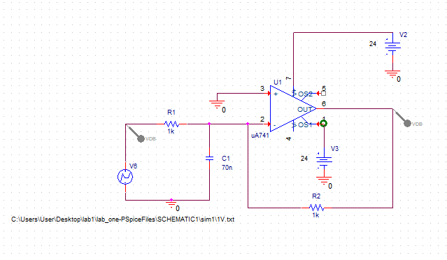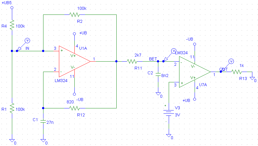
 Use probe to view the results graphically. Specify the step size, or time increment, to be used by Pspice. The duration of simulation depends on the time constants in the circuit. Sources: Vsin, Isin, Vpulse, Ipulse, etc. Pspice will simulate the time response of the circuit. Waveform (voltages or currents) versustime.
  Upper 3dB Freq=6.9 MHz Use calculations to prove this simulations!. can also be evaluated from this window (select Eval instead of View) In Probe: Trace/Eval Goal Function… Select: LPBW(1,db_level) Select: V(v_out) Enter 3 from the keyboard Click on OKįilter Design (3dB cutoff) – Example: Low Pass Filter to see a detailed explanation of this goal function and its parameters, select: Measure the f3dB point of v_out using a goal function Move other cursor until “dif” shows difference of 3dB. source p-to-p value during AC analysis Īpplication:Measure the f3dB point of v_out using the cursors. īODE PLOTS Magnitude vs Frequency Bode Plots Frequency Response Phase vs Frequency Passive Filter (has R,L,C components) Filter Active Filter (has active components e.g: BJT) normally operates as an amplifier. Applications: To see the frequency response of an amplifier and a filter. Analysis: Bode Plots, gain and phase plots, and phasor analysis. To find Magnitude and Phase of voltage and currents plots magnitude versus frequency plots phaseversusfrequency. Then, find the DC node voltages for the circuit. Solve the equation using Cramer’s Rule. Kirchoff’s Voltage Law = The algebraic sum of the voltages around a closed path is zero. Kirchoff’s Law Kirchoff’s Current Law = The algebraic sum of the currents entering a node is zero I1 I3 I2 I1 + I2 = I3 I1 + I2 – I3 = 0Ĭont. RESULT Max power transfer occurs when RL_val=1kohm Result: Max power transfer occurs when RL_val = 1kohm Setup a Parametric sweep (Analysis/Setup…/DC Sweep). Set up NAME1 and VALUE1 PARAM values (double-click on the symbol). Add a PARAM symbol (Draw/Get New Part…/ Param). Max Power Theorem: Max power occurs when RL = Rs. Objective: To analyze what value of Rs in the circuit that will deliver maximum power to RL. We can also display current through any device of the circuit vs V1.
Click V(Vo) : voltage at the node Vo vs V1.
If we use the DC Sweep, we can simulate the circuit for several different values of voltage / current source in the same simulation.ĥ.1 BASIC DC SWEEP ANALYSIS How does Vo vary as V1 is raised from 0 to 25 volts?ĭC SWEEP PROBE: Trace Add. The DC Sweep is similar to the node voltage analysis, but adds more flexibility. To find all DC voltages and currents of a circuit. Or you can click the V and I button to display the voltage and current. 
(shows the result of the node voltage analysis)Ĥ.1 BASIC DC NODAL ANALYSIS VIEWPOINT IPROBE The IPROBE and VIEWPOINT parts can be used to display the results of the Nodal Analysis On The Schematic.
Examine the output file: Analysis Examine Output. (shows the circuit connection and the number of node) Examine the netlist file: Analysis Examine Netlist. The results of analysis are kept in the output file. We will see that the IPROBE and VIEWPOINT parts display the results of the node voltage analysis. Simulate the circuit: Analysis Simulate. Create Netlist: Analysis Create Netlist. Calculate only DC currents and voltages. Every analysis begins with DC Nodecalculation. Monte Carlo Analysis (for component variations). Multisim is used for education purposes while PSpice is widely used in the industry. Can be used to design - Digital circuit - Analogue circuit - PCB design - IC design. Review Multisim – Digital circuit PSpice – Analogue circuit (electric / electronic circuit) Introduction to PSpice Syafeeza Binti Ahmad Radzi Computer Engineering Department FKEKK


